ProDiNo Ethernet V2

Do Not recommend for new design
You can replace ProDiNo Ethernet V2 (this board) with ProDino MKR Zero Ethernet V1
All the fun of a Leonardo, plus an Ethernet port, RS485 connection, 1 Wire input, some digital inputs and a few relays. It is the base device to extend your project to the IoT world. You can control sensors and actuators via the Internet as a client or a server. Also you can use it lots of and vary projects. We present you our KMP ProDino Ethernet V2 board:

Top

Bottom
The KMP ProDino Ethernet is a microcontroller board based on the ATmega32U4, the W5200 TCP/IP Embedded Ethernet Controller and the DS75176 supplies RS485 communication. It has 4 digital optical isolated inputs, 4 relays outputs, 3 digital and 2 analog input/output pins (of P1), a RS485 communication connector, a 1 Wire connector, a 16 MHz crystal oscillator, a RJ45 connection, a micro USB connector, an ISP header and a reset button. It contains everything needed to support the microcontroller; simply connect it to a computer with a USB cable or power it with a AC-to-DC adaptor to get started.
The ProDino Ethernet differs from the other boards in that the ATmega32u4 has built-in USB communication, eliminating the need for an external USB-to-serial converter. This allows the ProDino Ethernet to appear to a connected computer as a mouse and keyboard, in addition to a virtual (CDC) serial / COM port.
A Power over Ethernet (PoE) module can be add to the board as well.
Communication
The ProDino Ethernet has a number of facilities for communicating with a computer, another Arduino board, vary devices support RS485, Ethernet devices, sensors or other microcontrollers. The ATmega32U4 also allows for serial (CDC) communication over USB and appears as a virtual COM port to software on the computer. The chip also acts as a full speed USB 2.0 device, using standard USB COM drivers. On Windows, a .inf file is required. The Arduino software includes a serial monitor allowing simple textual data to be sent to and from the board. The RX and TX LEDs on the board will flash when data is being transmitted via the USB connection to the computer (but not for serial communication on pins 0 and 1).
The ProDino Ethernet appears as a generic keyboard and mouse, and can be programmed to control these input devices using the Keyboard and Mouse classes. The board can also connect to a wired network via Ethernet. When connecting to a network, you will need to provide an IP address and a MAC address. The other wired connection you can made through RS485 protocol. The RS485 communication supports easy link with many and different type of devices.

1 Wire, RS485 and 4 optical isolated digital inputs

4 relay outputs
Getting started
You can find in the Tutorial section all the information you need to configure your board, use the Arduino Software (IDE), and start tinker with coding and electronics. What you can do with this board see in our Examples.
Features
Specification
Dimensions

Pins mapping
Inputs/Outputs
RS485 port
W5200 control
1 Wire port
Additional connectors

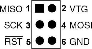
IPS (by a programmer)

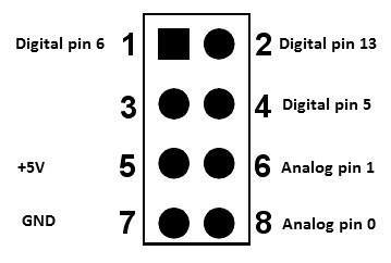
P1 connector

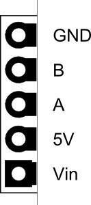
P2
Connector P2 is connecting only other RS485 devices.
How to power supply the board

What does the board consume?
Voltage | All relays off | All relays on |
|---|---|---|
6 V | 0.220 A | 0.300 A |
12 V | 0.120 A | 0.240 A |
24 V | 0.063 A | 0.127 A |
30 V | 0.051 A | 0.101 A |
Optical inputs with On state |
|---|
1.5 V - 2.5 mA |
5 V - 5.2 mA |
12 V - 6.0 mA |
24 V - 7.2 mA |
30 V - 7.7 mA |