ProDiNo Ethernet Tutorial
This ProDino Ethernet tutorial will help you to start with your board. The board details...
Table of Contents:
How to install a driver for an Arduino Leonardo
compatible board
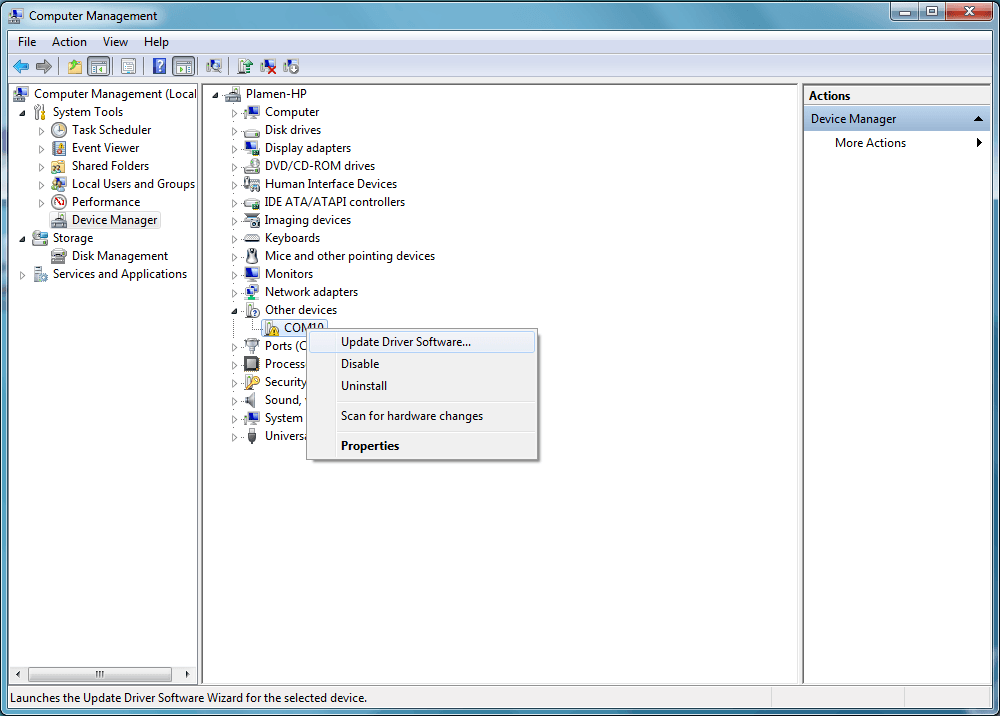
1. Opening the Device Manager

After you have already connected your board, you see a device with an yellow exclamation (!) sign. This is means that the USB driver for your board is not installed. From the context menu you have to select "Update Driver Software...":
2. "Update Driver Software..."
3. Then you see "Update driver software" window

4. Select: Browse my computer for driver software

Choice the folder where Adruino IDE is installed and select folder “drivers”.
6. If you sow this security windows you choose “Install…”

7. The driver has been installed successfully

You can see it in the Device Manager.

See also
How to set my Arduino IDE to works with a ProDino Ethernet (Arduino Leonardo) board
If you don't set the correct device in Arduino IDE, you can't Build and Upload your sketch example. Following the next steps to fix the problem.
1. Checking which COM port is installed our Arduino Leonardo board
If in the computer installed Windows on My Computer icon press the right mouse button. In the menu you are choosing "Manage". Then you should choose "Device Manager". If our Arduino Leonardo board is not installed in your computer and in your "Device manager" had a device with a yellow exclamation (!) sign, you can see above how to install it.
In this case the device is installed on the port COM12.
2. Opening the Arduino IDE and at the menu select Arduino Leonardo board

3. From the menu Tools/Port you select the COM port where is connected the device.
In this example the device is connected with COM12 port.

Installing ProDino Ethernet library
Base information about installation you can see here

2. Step two
Open your Arduino IDE. Of the horizontal menu - select: Sketch > Include Library > Add .ZIP Library

Version 1.0.x

Version 1.5.x
3. Select a .zip file KMPDinoEthernet.zip from your desktop and click Open

4. After the operation - the result is as follows

5. Restart (Close and Open) your Arduino IDE
The library examples can be found here: from the menu:
File > Sketchbook > libraries > KMPDinoEthernet.

Latest our library code you can see in GitHub: KmpDinoEthernet.h, KmpDinoEthernet.cpp
What can I do if I can't upload my sketch
When you tried to "Upload Example" and Arduino IDE threw similar error message likes as:

You check
- 1Is my board driver installed? See...
- 2Do I select appropriate at the board COM port? See...
- 3My board isn’t recognised. See...
- 4If you have uploaded sketch which uses Watch Dog. The Watch Dog is restarting the board before starting upload a new sketch. It can fix if in Setup section you add delay for minimum 30 seconds. In this case you should restore the BOOTLOADER on the board. See...
My board is not recognised
If you plug your board and it is isn’t recognised; (the board didn’t appear in device manager) - following next steps:
If previous steps don’t help you - check next:
How to I restore my BOOTLOADER on the board
- 1Getting USBtinyISP AVR Programmer
- 2Creating folder Avrdude
- 3Downloading and extract in folder Avrdude (AvrDude files) http://download.savannah.gnu.org/releases/avrdude/avrdude-6.1-mingw32.zip
- 4Downloading AvrDude GUI and extract in folder Avrdude https://sourceforge.net/projects/avrdudegui/files/latest/download
- 5Downloading Bootloader. Extract it in folder Avrdude (where a avrdude.exe file is) Caterina-Leonardo.zip
- 6Connecting your USBtinyISP AVR Programmer with ProDino ISP connector
- 7Start AvrDude GUI. Set settings - Avrdude.exe, programer(USBtiny), Port (USB), Device(ATMega32U4), Flash (Caterina-Leonardo.hex)
- 8Press button Erase-Write-Verify
- 9Upload your example through Arduino IDE
Some of the steps you can see here: http://www.hobbyist.co.nz/?q=usb-tiny-isp
Network configuration to test the example "Web Relay Control" for ProDino Ethernet
If your network is 192.168.1.x
To start a successfully example of ProDino Web relay control should have the following network configuration:

If your network IS NOT 192.168.1.x
If your network IS NOT 192.168.1.x
The local network may be in different ranges. For example: 10.0.0.0 - 10.255.255.255, 172.16.0.0 - 172.31.255.255, 192.168.0.0 - 192.168.255.255. If your network is different from 192.168.1. x, you won't have access to the board because it is located in a different range of addresses. Example: the network is 192.168.0.x.
The local network may be in different ranges. For example: 10.0.0.0 - 10.255.255.255, 172.16.0.0 - 172.31.255.255, 192.168.0.0 - 192.168.255.255. If your network is different from 192.168.1. x, you won't have access to the board because it is located in a different range of addresses. Example: the network is 192.168.0.x.

In this case, to able to access it you need to add your computer additional routing. Which becomes in the following way:
- Run Command Prompt (in Windows 7 and later versions with Administrator rights).
- Type the command:
route add 192.168.1.0 -p mask 255.255.255.0 192.168.1.199
This command adds a permanent entry in the routing table on your computer to access the IP: 192.168.1.199. - Press Enter to execute
The result should look like this:

Testing
For test whether the configuration is correct, do the following:
- Run Command Prompt.
- Type the command:
ping 192.168.1.199
With this command, check the connection on your computer with IP: 192.168.1.199. - Press Enter to execute
The result should look like this: